中文
中文 ENG
ENG


小优智能科技有限公司成立于2015年底,是一家专注于高精度3D机器视觉模组研发、生产及销售的高科技企业。
公司自主研发的3D机器视觉模组采用激光/DLP白光编码光栅结构光+双工业相机方案,还原物体三维信息,广泛应用于消费电子领域、工业领域和安防领域,具有精度高、速度快、成本低的优势。


For ease of understanding, the camera model is introduced from the perspective of physical imaging and
mathematical model.
1. Camera model (physical model)
Model of pinhole camera: The process of an object in the three-dimensional world being transformed into
a two-dimensional image through the camera imaging system is shown in Figure 1.
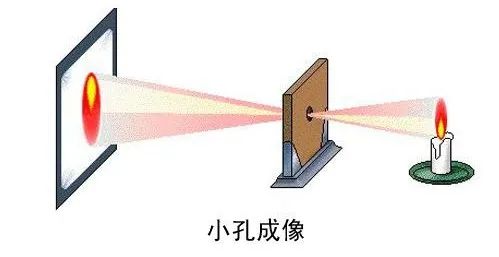
The physical model is shown in Figure 1. In fact, the entire imaging (camera shooting) process is apinhole imaging process, which does not involve four coordinate systems and coordinate system
conversion. In the real world, objects are imaged through the lens in the camera sensor, and
analog-to-digital conversion is performed to obtain a digital image. There is no mathematical calculation
in the whole process. Then the obtained image can be processed in various ways, such as image
recognition, target detection, image segmentation, etc.
If only image-level processing is done, it is enough to know so much. In the image measurement process
and machine vision applications, we need to know the correspondence between pixels and the real world.
At this time, we need to model the camera imaging process, and we must establish a geometric model of
camera imaging and find the parameters of this model.
2. Camera model (mathematical model/geometric model)
2.1 Coordinate system
To determine the relationship between the three-dimensional geometric position of a point in space and
its corresponding point in the image, and to model the camera imaging process, it is necessary to establish
a geometric model of camera imaging (various coordinate systems). The conversion parameters between
these coordinate systems are camera parameters. First, four coordinate systems are introduced. The
coordinate system is only a tool for camera modeling, and it is not constructed for no reason.
World coordinate system: The world coordinate system changes with the size and position of the object,
and the unit is the length unit; the coordinate system is represented by. Since the camera can be placed
at any position in the environment, a reference coordinate system is selected in the environment to
describe the position of the camera, and it is used to describe the position of any object in the
environment. This coordinate system is called the world coordinate system. The relationship between the
camera coordinate system and the world coordinate system can be described by a rotation matrix and a
translation vector.
Camera coordinate system: The origin of the camera coordinate system is the optical center, and the
unit is the length unit; the coordinate system is represented by.
Image coordinate system: The origin of the image coordinate system is the principal point (the
intersection of the optical axis and the image plane), and the unit is the length unit; the coordinate system
is represented by X and Y.
Pixel coordinate system: The origin of the pixel coordinate system is the upper left corner of the image;
the unit is pixel; the coordinate system is represented by .
2.2 Camera geometry model
After the coordinate system is established, the camera imaging process is abstracted into a coordinate
transformation relationship, as shown in Figure 2 below. The imaging process from three-dimensional to
two-dimensional can be described in mathematical language.
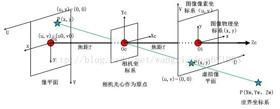
(1) The point in the pinhole is called the projection center;
(2) The intersection of the optical axis and the image plane is called the principal point;
The center of the imager is usually not on the optical axis, that is, the principal point is offset from the
center of the imager; therefore, two new parameters are introduced to represent the position coordinates
of the principal point in the pixel coordinate system. It is usually not exactly half of the image resolution, it
is offset, and the better the camera is, the closer it is to half of the resolution.
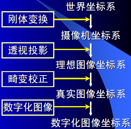
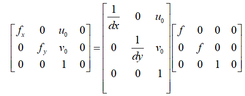
2.3 Camera mathematical formula model
The conversion process from the world coordinate system to the pixel coordinate system is as follows: the
world coordinate system is converted to the camera coordinate system through the external parameter
matrix, and the camera coordinate system is converted to the image pixel coordinate system through the
internal parameter matrix (this step is completed in two steps, (1) the camera coordinate system is
converted to the image physical coordinate system through the focal length diagonal matrix and the
distortion coefficient, (2) the image physical coordinate system is converted to the pixel coordinate system
through the pixel transformation matrix). The conversion process and formula are as follows:
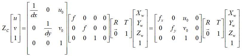
The internal parameter matrix can be expressed as:
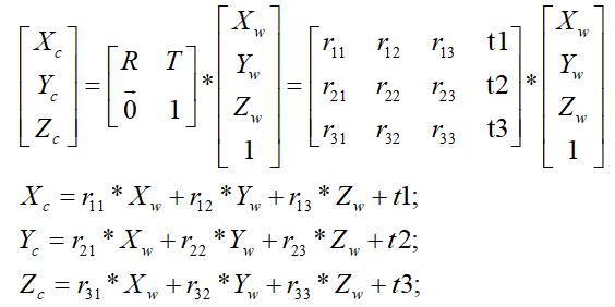
The external parameter matrix is expressed as: , where R is the rotation matrix and T is the translation vector. The detailed calculation is as follows:
The four steps of the camera optical imaging process: